I commented before that Nick Dolezal, who wrote Geigerbot, suggested that I use a noise offset of -13 CPM in my settings for the DRGB-90, which uses a SBM-20 tube (CPM conversion of 22 for Co60). Nick based this suggestion on the research of one of his collaborators, Higuchi Osamu, who did a series of experiments that showed that the SBM-20 had a noise floor of about +13 cpm.

UPDATE 2012.02.06: I have adjusted the correction factor done to -9 as of Feb 6th, see notes below

I was hesitant at first, but decide to do some more research on this. I eventually decided that having a noise offset was the right thing to do given the three sources of data that indicated this:

  1. Osamu Higuchi's research: http://www.higuchi.com/item/640
  2. Research done by the Kokumin Seikatsu Center on several consumer-level geiger counters (http://www.kokusen.go.jp/pdf/n-20111222_1.pdf). All of the SBM-20 based geiger counters (#3, #4, and #5) read around 0.05 - 0.07 uSv/hr high on background radiation, as well as 0.05 - 0.08 uSv/hr too high when they were inside a lead-lined container. This means that the SBM-20 is occasionally firing even when there is no radiation and that these consumer units do not compensate for inherent background counts. See page 7 of the report.
  3. Finally, when I use a compensation factor of -13 CPM along with a conversion factor of 22 (Cobalt-60), my DRGB+Geigerbot values very closely align with both the national and city government's figures for Shinjuku ward, where I am, namely around 0.05 uSv/hr.


Here's the national and city government data:

All of them seem to be giving figures of about 0.05 uSv/hr (+/- 0.2 uSv/hr) which is exactly what my compensated Geigerbot reading is. So I'm now confident that I'm getting fairly good data.

Another way to read the data is the highest radiation readings for Shinjuku for the past year was March 22, 2011 when the maximum atmospheric reading was 0.166 uGy/h (equivalent to 0.166 uSv/hr). Without the compensation factor, I was getting these levels every day! So obviously my uncompensated geiger counter was reading high.

p.s. I would like to publicly state for the record that Nick Dolezal rocks.


Note 1: 1000 nSv = 1 uSv ===> so 50 nSv/hr = 0.05 uSv/hr
Note 2: 100 nSv/hr or 0.10 uSv/hr ===> 877 uSv / year or .9 mSv / year


DRGB90 mod 001

I've been spending the past couple of months in Tokyo. Worried about the radiation, I brought my DRGB-90 russian geiger counter /dosimeter that I had bought a couple of years ago. Unfortunately, the DRGB is a rather old analogue design and the readings at low (natural background radiation) are rather imprecise.

There's an application on iOS called Geigerbot that is a sophisticated click-counter. Set up correctly, it can give you precise microsievert per hour readings. It also interfaces with Pachube which allows historical readings. Now Geigerbot can use the microphone on your iPad/iPhone to detect the geiger counter's audible clicks, but it will of course also pick extraneous external noise.

I wanted to directly interface my DRGB-90 with my iPhone so I could have more precise readings. Unfortunately, the DRGB doesn't have an external speaker jack or any other outputs.

Here's how I hacked it.


Step 1: Take it apart

It's very important to note that geiger counters produce very high voltages (400 volts in the case of DRGB-90). Before opening the case, remove the batteries. This is what it looks like on the inside. The long cylinder is the SBM-20 geiger-muller tube. It came wrapped in aluminum foil from the factory in order to give it better shielding against beta radiation (in order to emphasize gamma radiation).

DRGB90 mod 003

I was disappointed to not see the speaker when I opened it up. Hmm, it must be on the back side of the printed circuit board. The board didn't up easily, it took some wrenching

Step 2: Under the PCB

Lifting up the PCB (with the help of a sharp scoring knife to break the PCB conformal coating). The piezo speaker becomes visible. I wanted to patch into the speaker. Using my multimeter, it becomes clear that the piezo speaker frame is grounded to ground and there's a small (almost invisible in the photo) lead to the piezo.

DRGB90 mod 004

Step 3: Patching into the speaker output

I cut the speaker output lead and soldered in my own lead.

DRGB90 mod 007

Step 4: The speaker jack

I then hacked in my own headphone jack using the lead from the piezo speaker as the positive terminal and the battery ground as the ground. On the headphone jack end, I used the necessary bypass capacitor and voltage dividing resistors that the iPhone needs to recognize a microphone input, as noted on the Geigerbot homepage. I could have built this into the unit itself if I had thought a bit more about it. In order to reduce the output to iPhone mic-in levels, I used the 100:1 voltage divider circuit on Higuchi's page, but the volume levels were a bit low in Geigerbot, so I later changed it to 40:1 by swapping out the 100K resister.

DRGB90 mod 009

Step 5: Putting it all together

Here it is all put together and hooked into my old iPhone 3G which had been previously destined for the dust box.

DRGB90 mod 002

The iPhone then connects into my Pachube account for a real-time and historical data feed.


Tim writes asking how he could charge his 8S2P Prius battery pack used in an experimental EV. My Piaggio is 6S2P and I encountered numerous problems. Here was my response to him:

Using Prius packs are tricky and 8S2P is going to be even more difficult. Here are the problems:

  1. Charging voltage is very high

  2. Even "smart" chargers cannot detect Prius battery delta-V or delta-T to stop charging
  3. No parallel charging
  4. Packs expand on charging

* High voltages

Prius NiMH batteries are internally 6 cells, so a 6S pack is really a 36 cell pack, with nominal voltages of 43.2 volts (but usually hot off the charger at around 50 volts). An 8S pack would be 48 cells, so nominally 57.6 volts with a hot off the charge voltage above 60 volts.

Then the problem is that almost all commercial NiMH chargers go up to 50V (and even those are rare). I had trouble finding chargers for my 36-cell pack. The two I bought were: Astroflight 112D (NiMH version) and the "CH-UN4820 Multi-Current Smart Charger (2.0A) with 3 pins Plug for 36V or 48V NiMH / NiCd Pack."

You will most likely have to split your pack in half so you only charge 4S (24 cells) at a time.

* No parallel charging

First, you know you should never charge in parallel, so you need to add some connectors so you can charge as two 8S1P and 8S1P packs -- or four 4S1P packs. I recommend Anderson 75A power pole connectors.

* Smart chargers can't detect Prius delta-T/V

NiMH batteries are tricky to charge as there isn't a fixed final voltage as with LiIon/LiPo/Lead-acid. Instead, smart chargers usually look for a very small drop in voltage (delta-V) which signals the cell is full; or an increase in cell temperature (delta-T).

Unfortunately, Prius packs don't exhibit a measurable drop in voltage and don't increase in temperature when they are full. This is partly because of their pack design (prismatic rather than cylindrical). Instead, when a Prius pack is full, it bulges due to the increased internal pressure. Not good.

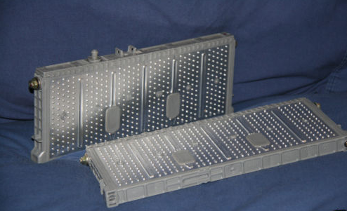
* Packs expand when charged

The prismatic (rectangular) Prius packs will swell and expand when they are overcharged. In order to prevent this, you have to design a strong battery holder that will keep good lateral pressure on them. My own holder (below) uses threaded rod and steel plates to hold the packs together. Even with 2mm steel, the packs have put enough pressure on the side plates to bend them and I'll have to make up new side plates sometime soon.


* How to charge

So how do you charge a Prius pack? I haven't found a smart charger smart enough to charge them using the standard delta-T and delta-V. So instead, I do what the battery management system in the Prius does -- I coulomb count. With my CycleAnalyst, I know how many watt-hours I've used in a ride. For example, for my commute I used 234.23 Wh which is around 5.90 Ah.

Knowing that my multi-current "smart" (stupid) charger has a nominal charge rate of 2.0 amps (and using a wattmeter), I set the charger using a timer to charge for 3 hours. This gives me 3 hours x 2 amps = 6 amp hours.

I have to repeat this twice, one for each side of my parallel chain.


I'm in the process of designing my own charge circuitry that will allow me to automate the coulomb counting. It will measure the output of the battery, then put the same back in (+10% for charging inefficiency). For a backup foolproof end-of-charge detection, I plan on using load cells to detect when the cells are expanding from internal pressure.

Of course, I'm busy with my day-job so this advanced Prius pack charger is still many many months (if not years) away given that a simple charger with a timer does much the same.

Trés cool programming of an ultra-cheap ATtiny 45/85 using the Arduino IDE. Perfect for embedded systems. Now there's no reason for me to go back to PICAXE!

This tutorial shows you how to program an ATtiny45 or ATtiny85 microcontroller using the Arduino software and hardware. The ATtiny45 and ATtiny85 are small (8-leg), cheap ($2-3) microcontrollers that are convenient for running simple programs. They are almost identical, except that the ATtiny85 has twice the memory of the ATtiny45 and can therefore hold more complex programs. We like to use both of them with paper circuits and other craft electronics. To program them, we’ll use a port of the Arduino core libraries created by Alessandro Saporetti and slightly modified by HLT.

From: http://hlt.media.mit.edu/?p=1229

Have been playing with the Seeeduino Bluetooth module. Will report more later, but just wanted to note that there's a simple UNIX command to turn your terminal into a … terminal on another port:

Knowing the serial port, you can just type screen portname datarate to show the serial data on the screen. In my case, it was:

screen /dev/tty.Keyserial1 9600

Then I started typing bytes at the PIC, and it sent bytes back to me. Whee! No need for zTerm! To quit the screen app, type control-A, then control-\.

Very useful!

From: http://www.tigoe.net/pcomp/resources/archives/avr/000749.shtml

PHilips LED3 540x378

EDN.com has a great two part teardown of the new Philips AmbientLED 12.5W lightbulb. I use these A19 style bulbs in my house. They have a nice even white-light output, dim much better than the other LED bulbs I've used. All around, great players. And CL&P has an instant rebate for them in CT that makes them $20 each.


What's really neat about them is that they use remote phosphor technology. The yellow coating on them fluoresces under the blue LED used internally in the devices. This allows for the diffuse white quality of the light. This is in contrast to the CREE LEDs that have the secondary phosphor built into the LED shell itself and a diffuser in the A19-style shell. Their luminous efficacy is actually much better than CFLs for a change.

UnitWattsLumenslm/WPrice
Eco-Smart8.6 W420 lm49 lm/W~$20
Philips AmbientLED 12.5W12.5 W800 lm64 lm/W~$20 AIR
Compact 16W CFL16 W800 lm50 lm/W~$2

RemotePhosphor

Boxer EV v4 Photos

| | Comments (3)

I thought I would post some images of the latest iteration of my Piaggio Boxer EV project. I hadn't actually shown the Prius batteries mounted, even though I had done that almost a year and a half ago.


This is the front, showing new 9 watt LED front bulb. Blindingly bright:

PiaggioBoxerEV4 001


This is the Prius pack mounted in the 6s2p configuration, given me 43.2 volts @ 13 Ah nominal. I made the battery carrier myself. The motor speed controller is below the pack, but it's hard to see from this angle:

PiaggioBoxerEV4 002

This shows the new style HobbyKing motor mounted. The new motor was longer than the old one (even though the specs on HobbyKing's site weren't updated) which meant it could no longer fit in the old motor mount. I had to weld together my own motor mount. Right now, I'm holding the motor only on one side, leaving the other open for the cooling fan (made from a PC computer fan) - note that the motor spins counter-clockwise from this perspective, so the fan draws air into the motor. I think I'll eventually end up making a retention bracket for the right side as well, to prevent too much stress on the bearings on motor:

PiaggioBoxerEV4 003

This left hand side shows how the motor was moved forward in order to fit:

PiaggioBoxerEV4 004

A little view of the wonderful CycleAnalyst:

PiaggioBoxerEV4 005


This is the new reverse-current board that I made using MOSFETs. It's not perfect, but it's more efficient than the blocking diodes that I used -- which were expelling 1.7 volts @ 100 amps == 170 watts when the motor was at full speed!


PiaggioBoxerEV4 006

Ending with another side view.

PiaggioBoxerEV4


From the "I wouldn't believe the physics even if I saw the youtube video" department, a sail car that can go faster downwind than the wind itself. While it's possible to go faster than the wind when tacking against it, it was long thought to be impossible to faster directly downwind. These folks prove it's not so:


Some links to enjoy:

There are a couple of free (as in beer) programs that can help you draw up wiring diagrams or schematics. Some of them will even turn them into PCB templates for you. These are the ones I've used:

Fritzing: Fritzing is designed to work with Arduino systems, but is still very much in alpha. Still, I use it for quick and simple schematics of my Arduino projects as it has most of the wiring all set to go.

Eagle: This is the program most serious people seem to be using. I find its interface to be extraordinarily complex and non-intuitive. There's a free version with just a few limitations, or pay for the real version with none. Can export to PCB templates.


Any suggestions on other alternatives? I'm a Mac user, so I only listed the Mac-compatible ones here. I know that other folks use ExpressPCB and some other programs that are Win-only.

Find recent content on the main index or look in the archives to find all content.

Recent Assets